
Cable
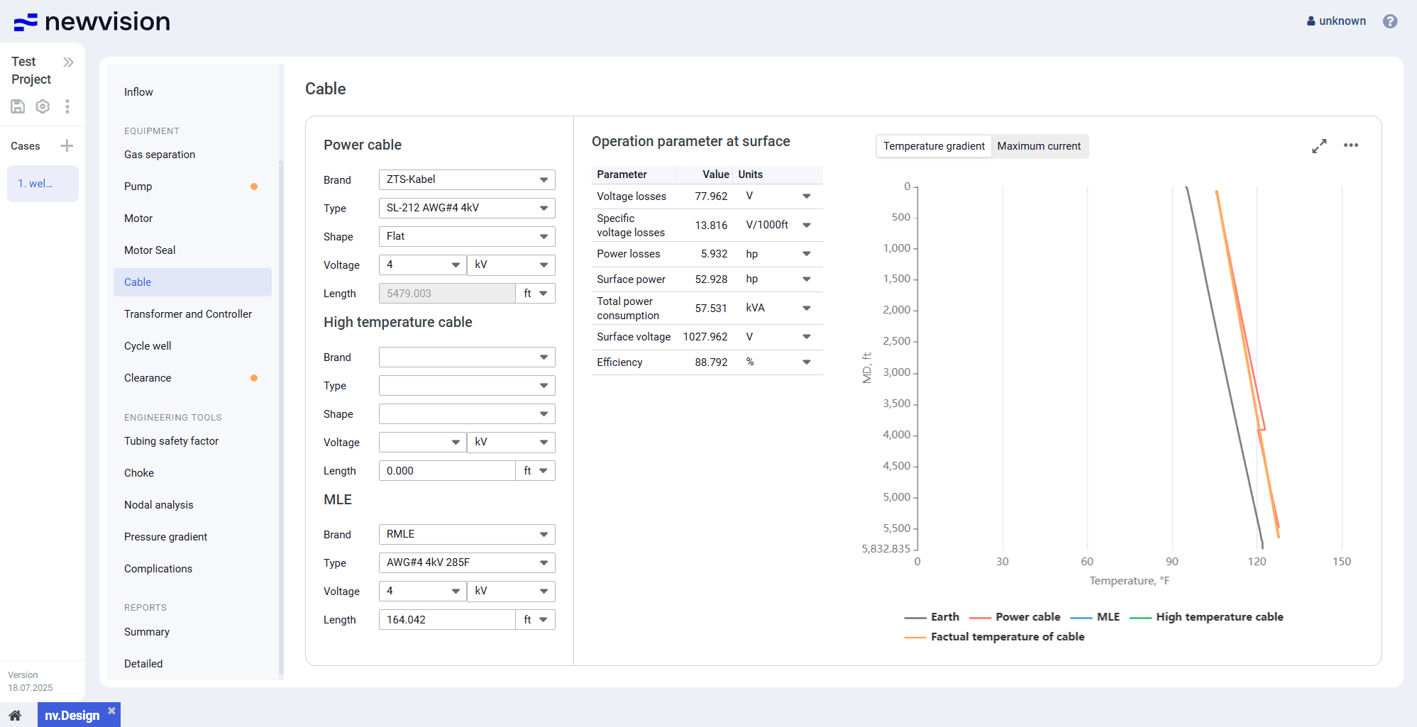
Cable: The Cable section provides information about the cable. You can configure up to three cable segments. The section consists of the following parts: Power cable , High…
The Cable section provides information about the cable. You can configure up to three cable segments.
The section consists of the following parts:
- Power cable, High temperature cable, and MLE parameter groups in the left part of the section.
- Operation parameter at surface table in the central part of the section.
- Visualization pane in the right part of the section.
 Select image to enlarge
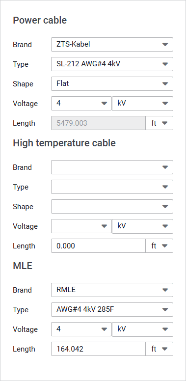
Power Cable, High Temperature Cable, and MLE
These parameter groups provide controls for selection and configuration of the cable segments.
 Select image to enlarge
Power cable
This is the main parameter group. Power cable is typically laid from the surface to the ESP setting depth. Its length is calculated automatically and equals the installation depth specified in the Wellbore section. For details, see Wellbore configuration.
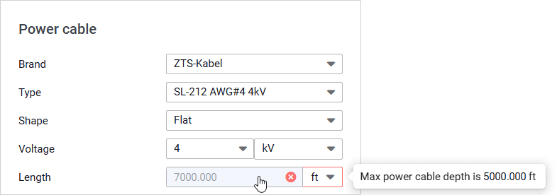
The system also provides a warning mechanism that evaluates the maximum allowable cable power cable length based on the temperature down the wellbore. If the wellbore temperature exceeds the power cable's maximum nominal value, the error icon ( ) is displayed. In this case, a high-temperature cable must be used.
For example, if the ESP setting depth is 7 000 ft and the tooltip says ‘Max power cable depth is 5 000 ft’, that means that a high-temperature cable and/or motor lead extension (see description below) must be used for 2 000 ft.

 Select image to enlarge
High temperature cable
High temperature cables are recommended for high-temperature zones (e.g., due to hot fluid, high reservoir temperature, or significant operating currents) where considerable heat generation may occur.
Such cables are designed for enhanced thermal resistance and should be routed from the ESP setting depth to the depth at which the temperature becomes acceptable for a standard power cable.
MLE (Motor Lead Extension)
Extensions are used in the pump setting zone to connect the cable to the motor with a transition to a different thermal rating.
 | Note |
Operation Parameter at Surface
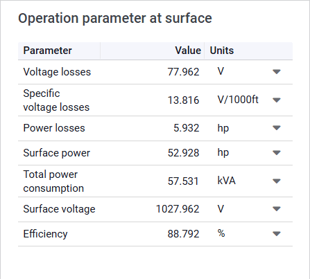
The Operation parameter at surface table provides calculation results for the selected cable configuration.
 Select image to enlarge
Visualization Pane
The pane consists of two charts distributed on different tabs:
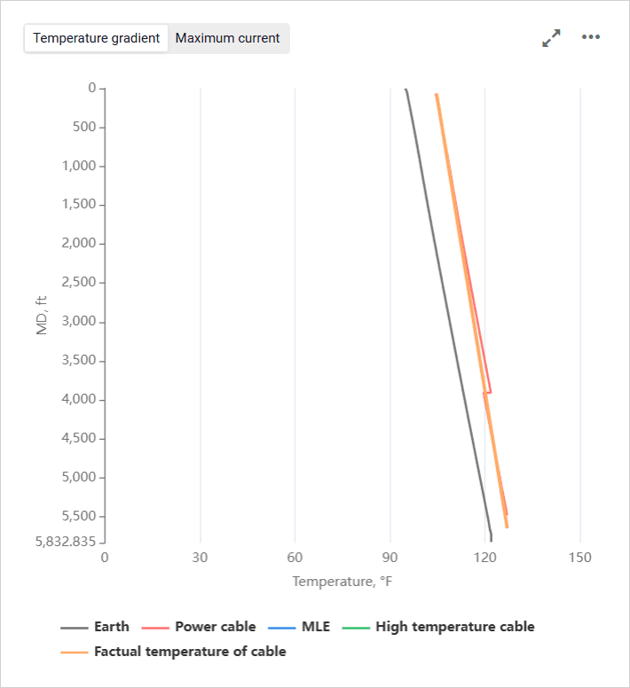
- Temperature gradient: Chart representing submersible electric cable.
The Power cable, MLE, and High temperature cable curves account for the following physical phenomena: temperature jumps when transitioning from gas to liquid, splices, insulation and armor losses, annulus thermal gradient considering inclination, etc.
The Factual temperature of cable curve reflects the dynamic longitudinal redistribution of temperature over time along the entire cable length.
 Select image to enlarge
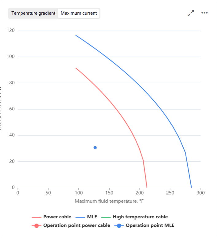
- Maximum current: Chart representing dependence of the allowable current on the maximum temperature of the well fluid.
 Select image to enlarge
To show or hide a parameter on the chart, click the parameter name under it.
On hovering over any point on the chart, a window with information about the exact parameter values at this point is displayed.
You can also expand the pane to full screen or collapse it back to the original size using the Expand ( ) / Collapse ( ) buttons located in the upper-right corner of the pane.

