
Pump selection and configuration
Pump selection and configuration: Pump The Pump section provides information about the pump and target calculation parameters. This is the key section to which the equipment…
On this page
Pump#
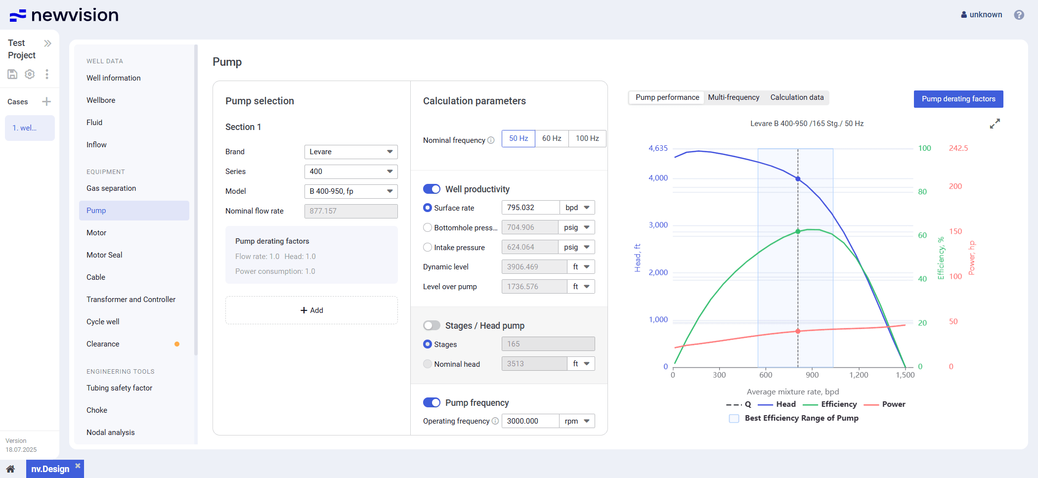
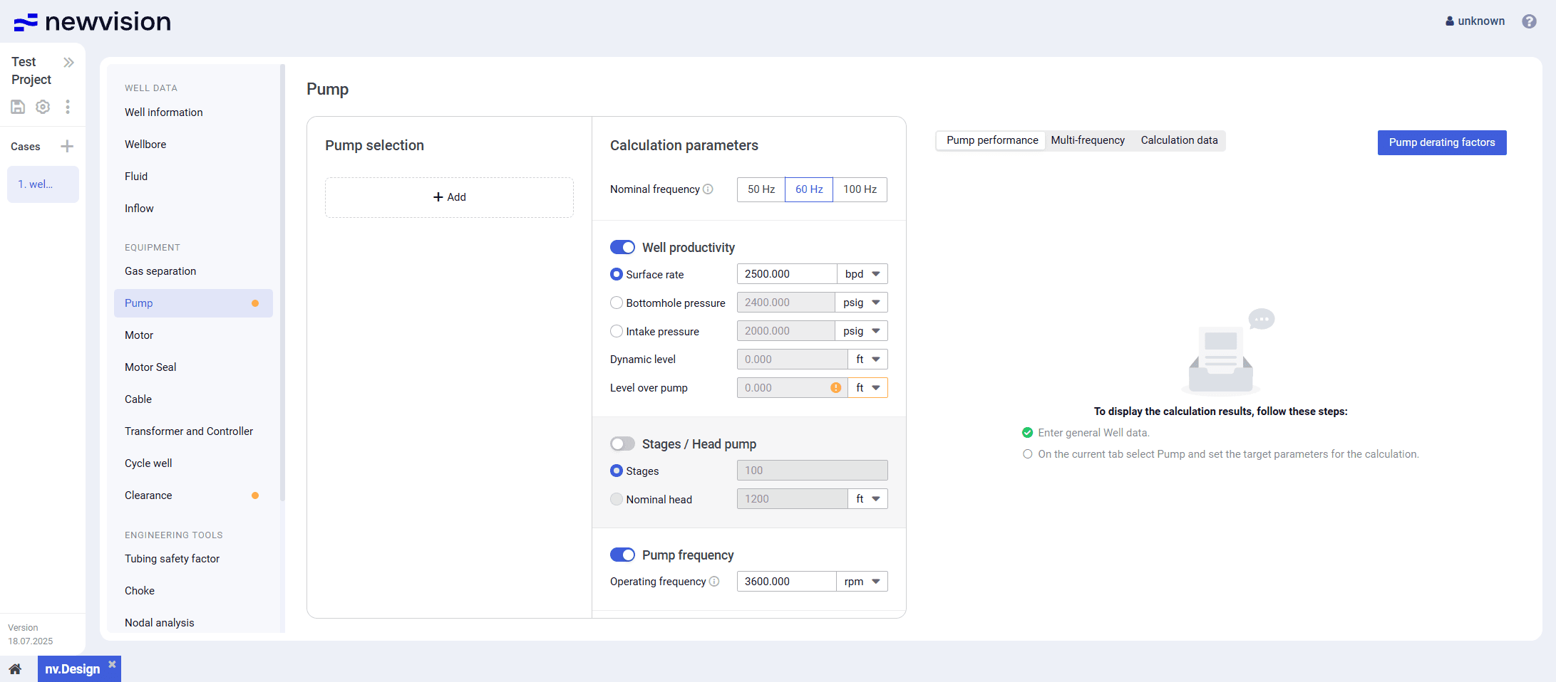
The Pump section provides information about the pump and target calculation parameters. This is the key section to which the equipment data must be added.
For details, see Configuring Pump Parameters.
The section consists of three panes:
- Pump selection pane in the left part of the section.
- Calculation parameters pane in the central part of the section.
- Visualization pane in the right part of the section.
 Select image to enlarge
Pump Selection
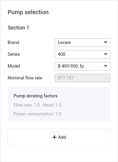
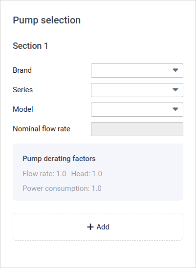
In this pane, you need to select a pump or several pump sections. To do this, click Add ( ), and then select the pump parameters from the corresponding lists.

 Select image to enlarge
At the bottom of each pump section, the Pump derating factors area is displayed. The default derating factor value is 1, which means the section is operational and working normally. You can edit the derating factor values in the Derating factors window. For details, see Configuring Pump Parameters.
Calculation Parameters
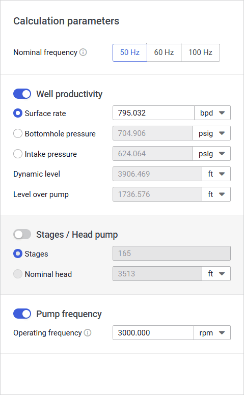
In this pane, you can configure target parameters of the pump that are required for the calculation.
 Select image to enlarge
The pane contains three parameter groups:
- Well productivity
- Stages
- Pump frequency
You can select only two of these groups at the same time, the third will be calculated automatically. In case of conflicting inputs, other values are automatically recalculated.
 | Important 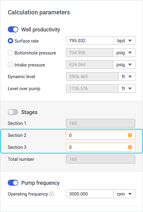 Select image to enlarge Select image to enlarge |
To select or deselect a parameter group, use the toggle to the left of the group name.
If only one pump section is selected in the Pump selection pane, at the top of the pane, the Nominal frequency parameter is displayed. Its value is used for calculating the pump’s nominal flow rate and nominal head.
By default, the 50 Hz option is selected.
Well productivity
In this group you can select one of the following target parameters and specify its value: Surface rate, Bottomhole pressure, or Intake pressure.
The Surface rate value is taken from the Inflow section. For details, see Inflow.
Stages
In this group, you can specify the number of stages of each pump section.
If there is only one section, instead of the number of stages, you can enter the nominal head value. The other parameter value is calculated automatically. If the number of stages is specified, the nominal head is calculated based on the catalog value obtained from the pump testing with water.
Pump Frequency
The group contains only one parameter, Operating frequency. By default, its value is set to 3600 rpm.
Visualization Pane
The pane contains charts that visualize pump operation characteristics.
Depending on the number of pump sections, the pane may consist of different tabs.
If there is only one pump section, the following tabs are available:
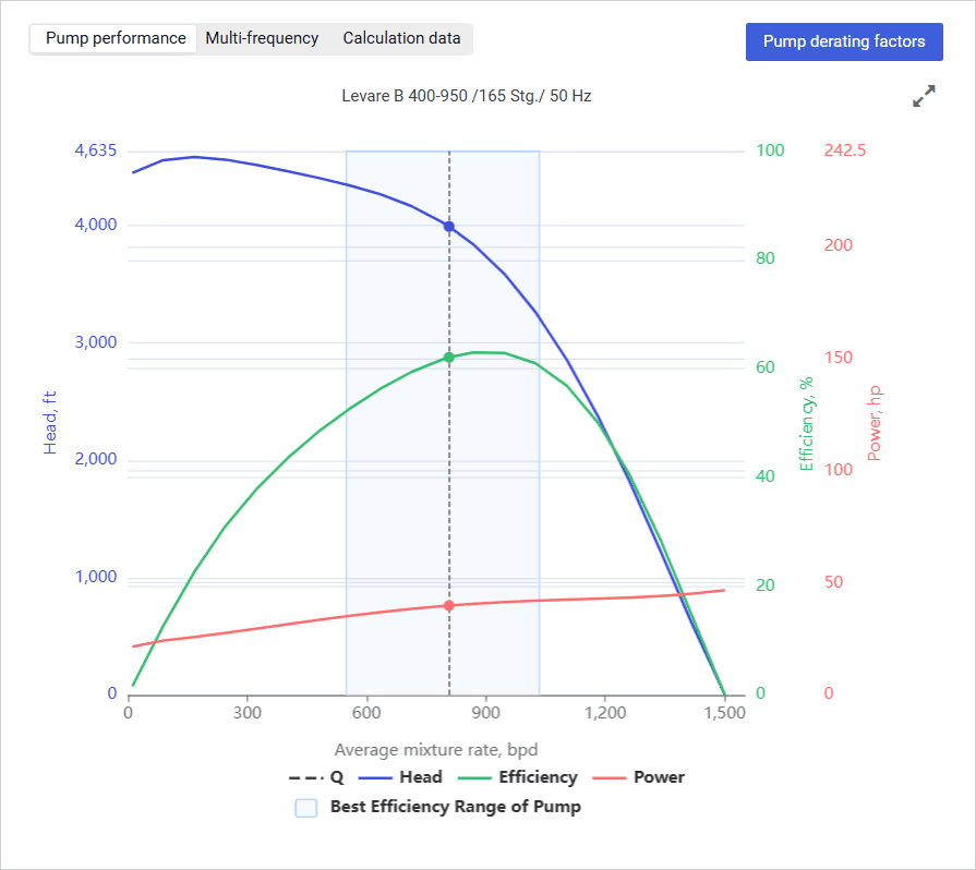
- Pump performance: Provides the pump H-Q (head-flow) curve with values of the pump flow rate, head, efficiency, power, and operating range.
 Select image to enlarge
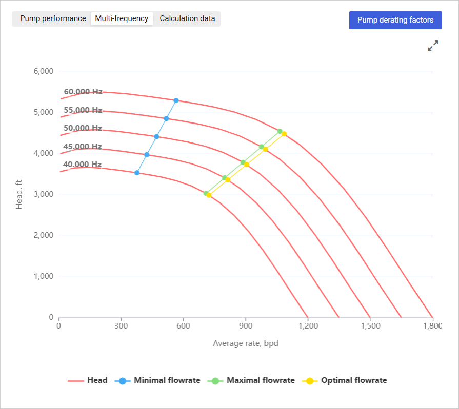
- Multi-frequency: Provides graphs of the pump head at various frequencies.
 Select image to enlarge
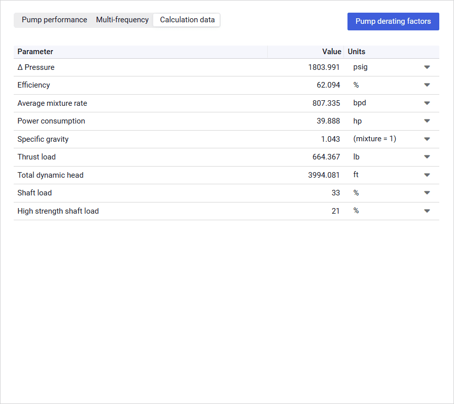
- Calculation data: Provides a table with values of the pump’s pressure differential, efficiency, power consumption, shaft load, etc. These parameters help to select the most suitable motor, motor seal, cable, and surface equipment.
For example, the Thrust load value can be used to select a motor seal so that the thrust bearing load remains within acceptable limits.
 Select image to enlarge
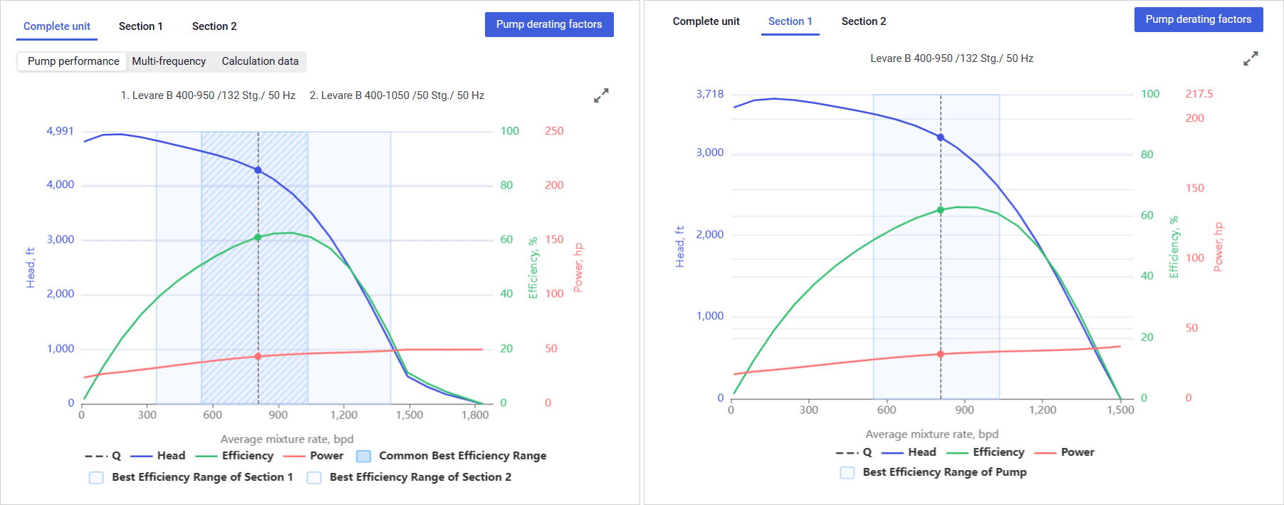
If there are two or three pump sections, the following tabs are available:
- Complete unit: Contains the same sub-tabs as a single-section pump (see description above) with integrated data for the whole pump configuration.
- Section 1: Provides the same data as the Pump performance tab (see description above) with the H-Q (head-flow) curve for the specific pump section.
- Section 2: Same as Section 1.
- Section 3: Same as Section 1.
 Select image to enlarge
To show or hide a parameter on the chart, click the parameter name under it.
On hovering over any point on the chart, a window with information about the exact parameter values at this point is displayed.
You can also expand the pane to full screen or collapse it back to the original size using the Expand ( ) / Collapse ( ) buttons located in the upper-right corner of the pane.


Configuring Pump Parameters#
To configure parameters of the pump installed in the well, perform the following actions:
- Open the nv.design module.
For details on navigation in the system, see System Interface. - In the left part of the working area, in the list of the module sections, click Pump.
To the right of the list, the Pump section opens.
 Select image to enlarge
In the Pump selection pane, click Add ( ).
The Section 1 parameter group appears.
 Select image to enlarge
- Under the Section 1 heading, select a manufacture, series and model of the first pump section from the corresponding lists.
- (Optional) To add one or two more pump sections, repeat Steps 3–4.
- (Optional) To edit pump derating factors for the pump sections, perform the following actions:
- In the upper-right corner of the section, click Pump derating factors.
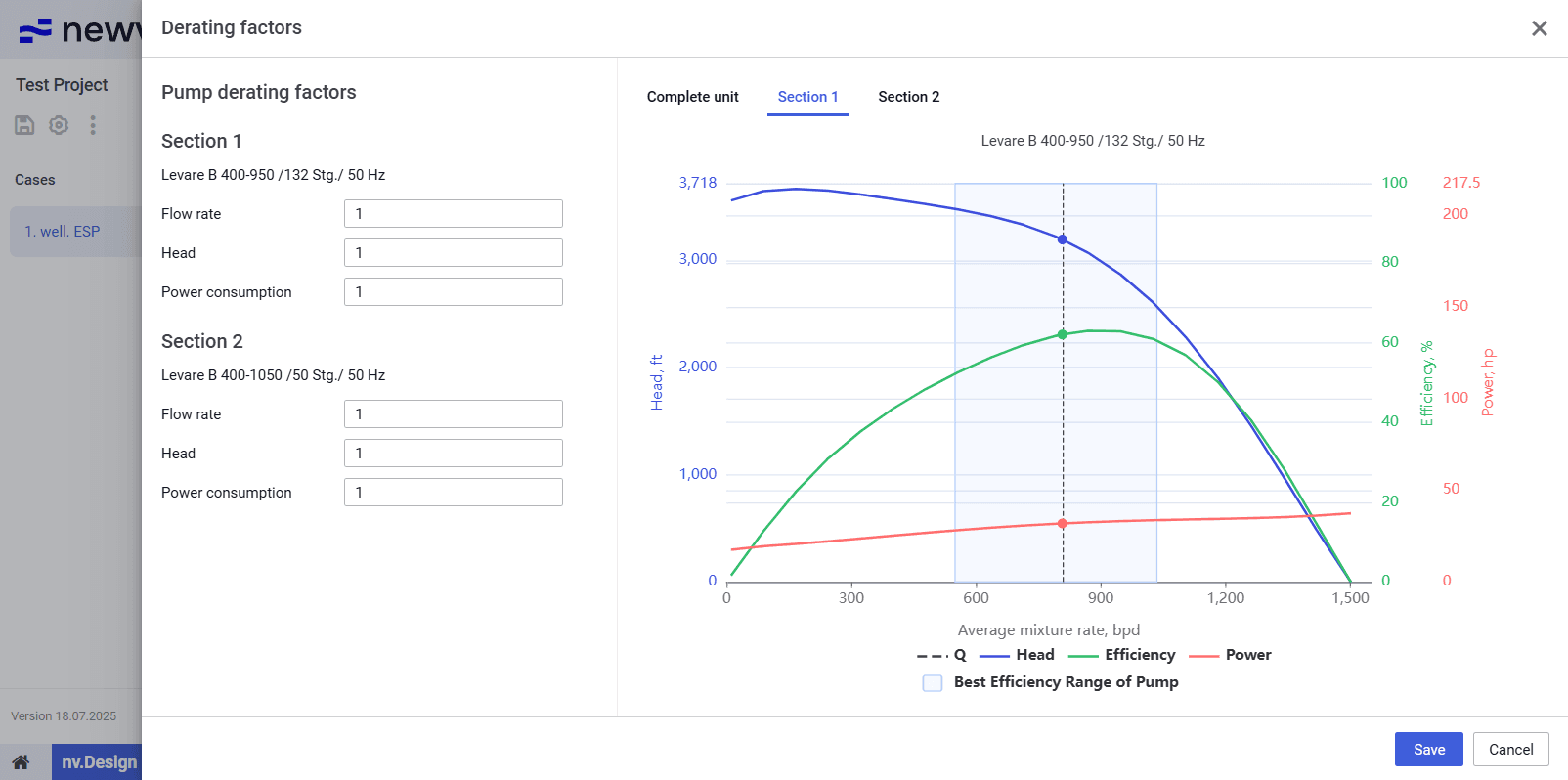
The Derating factors window opens.
 Select image to enlarge
- In the window that opens, in the Flow rate, Head, and Power consumption fields, enter the derating factor values for the desired pump sections.
In the right part of the window, tabs with charts representing the pump operation characteristics are adjusted according to the entered derating factors. For details on these charts, see .
Warnings, if there are any, are displayed below the charts.
 | Note |
- At the bottom of the window, click Save.
- In the Calculation parameters pane, enable two of the three parameter groups based on which further calculations will be performed. To do this, use the toggle to the left of the group name.
Select image to enlarge- Depending on the selected groups, perform the following actions:
- (For Well productivity) Select the target parameter (Surface rate, Bottomhole pressure, or Intake pressure) and specify its value.
The other group parameters are calculated automatically. - (For Stages) Depending on the number of the pump sections, perform one of the following actions:
- If there is only one section, select the parameter based on which the calculation will be performed (Stages or Nominal head) and specify it value.
The other parameter is calculated automatically. - If there are two or three sections, specify the number of stages for the second and the third sections.
- (For Pump frequency) Specify the pump operating frequency.
The default value is 3 600 rpm.
| Note Select image to enlarge |
- After the configuration is completed, in the right part of the section, charts representing the pump performance are displayed. For details on the charts that are displayed in the visualization pane, see .
To save changes, in the left part of the module, click Save ( ) under the name of the current project.
