Configuring DLS
Configuring DLS: To configure the well tubing and casing parameters, perform the following actions: Open the nv.design module. For details on navigation in the system, see…
To configure the well tubing and casing parameters, perform the following actions:
-
Open the nv.design module. For details on navigation in the system, see System Interface.
-
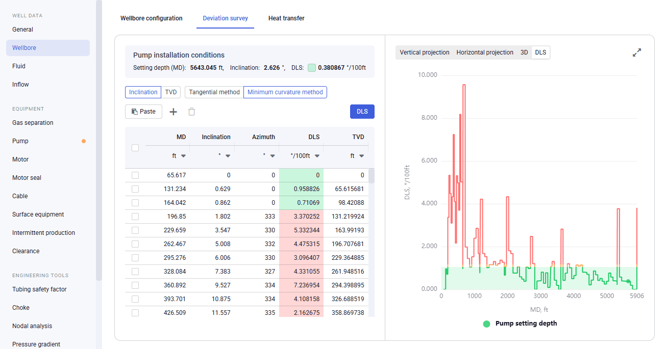
In the left part of the working area, in the list of the module sections, click Wellbore, and then go to the Deviation survey tab.
 Select image to enlarge
 -
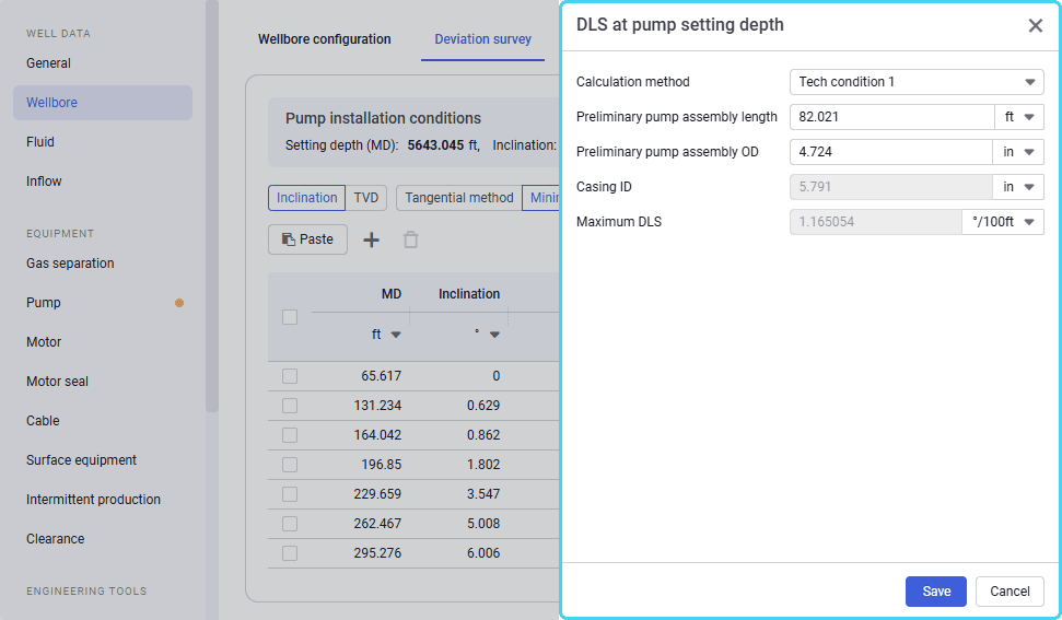
At the top of the pane in the left part of the section, click DLS. The DLS at pump setting depth window opens in the right part of the section.
 Select image to enlarge
 -
In the window that appears, perform the following actions:
-
From the Calculation method list, select one of the following calculation methods:
-
Tech Condition 1: Simple empirical linear formula that is based on the difference between the inside diameter of the casing and the outside diameter of the installed equipment, taking into account the entire pump assembly length. This method provides a quick and approximate result and is most suitable for quick operational assessment.
-
Tech Condition 2: More complex nonlinear formula using the asin function. It accounts for the interdependence between the diameter difference and section length. It provides a more accurate estimate of geometric curvature and actual mechanical stresses affecting the ESP. This method is recommended for technical condition calculations and verification of the installation safety.
-
-
(Optional) Edit the default values in the Preliminary pump assembly length and Preliminary pump assembly OD fields. Values in the Casing ID and Maximum DLS fields are calculated automatically.
-
At the bottom of the window, click Save.
-
-
To save changes, in the left part of the module, click Save (
 ) under the name of the current project.