
Checking equipment clearance
Checking equipment clearance: Clearance The Clearance section provides information about the equipment dimensions and the minimum required clearance. This data is required to…
Clearance#
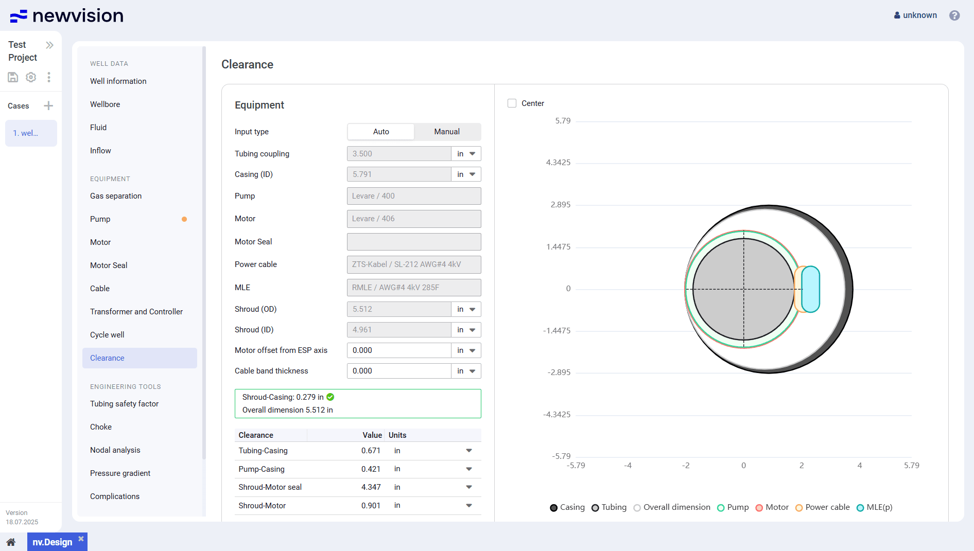
The Clearance section provides information about the equipment dimensions and the minimum required clearance. This data is required to ensure that all downhole equipment can be safely run into the wellbore.
The section consists of the following parts:
- Equipment pane in the left part of the section.
- Visualization pane in the right part of the section.
 Select image to enlarge
Equipment
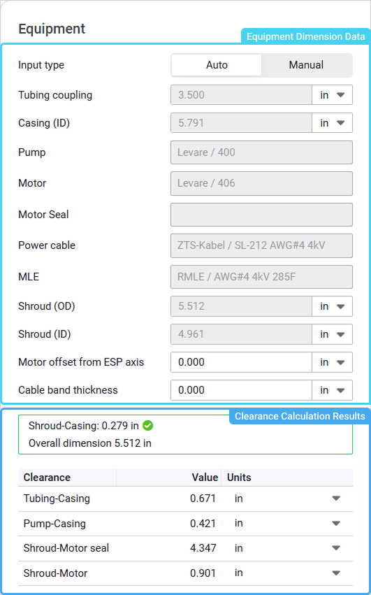
The pane is divided into two parts:
- Equipment dimension data in the upper part of the pane.
- Clearance calculation results in the lower part of the pane.
 Select image to enlarge
To select a method of the equipment dimension data input, select the desired option of the Input type parameter:
- Auto: Data is filled in automatically from other nv.design module sections.
- Manual: Data is entered manually to perform preliminary clearance checks to determine whether clearance values fall within acceptable limits even before detailed calculations are performed.
In the lower part of the pane, there is a table with the clearance calculation results.
At the top of the table, the summary data is displayed:
Equipment clearance: Minimum clearance between the assembly components (taken from the table below).
Green check mark ( ) next to the value indicates that the clearance is sufficient for feasibility and operational safety of the installation process.
Red cross ( ) means that the clearance is too small and must be fixed.

- Overall dimension: Maximum outer diameter of the entire assembly based on the equipment dimensions.
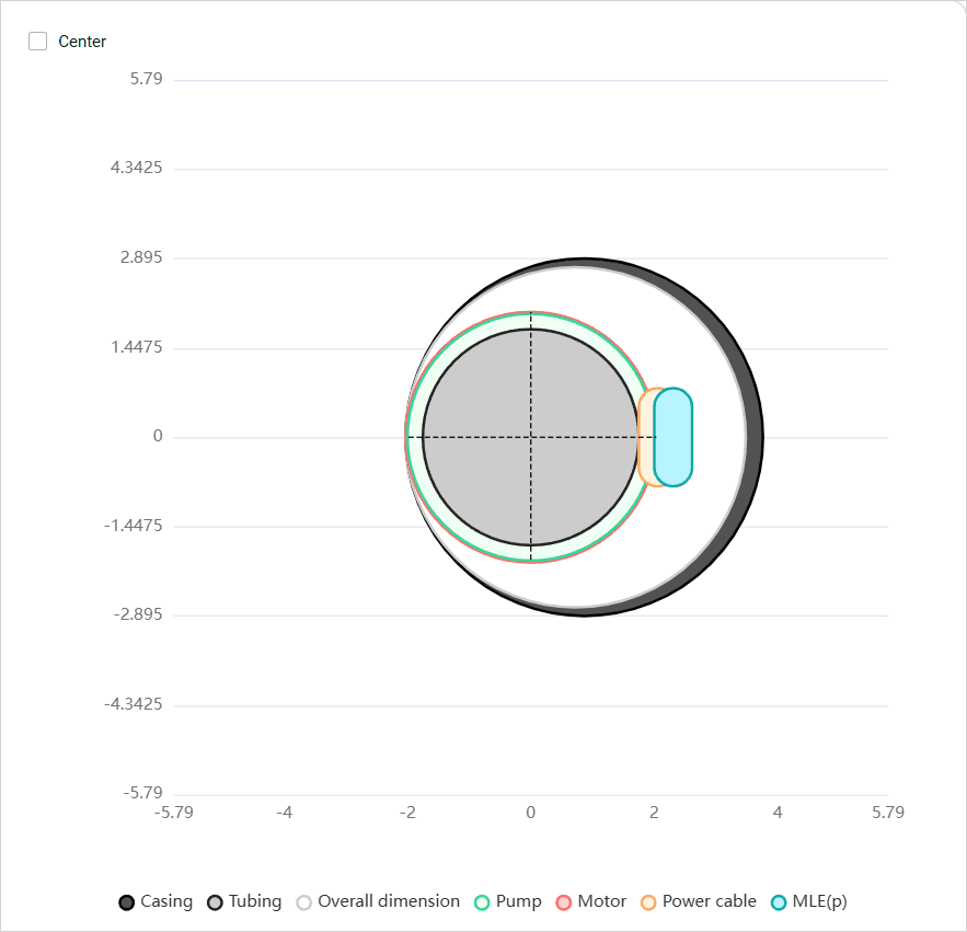
Visualization Pane
The pane contains a simplified layout of the ESP string inside the well.
 Select image to enlarge
You can adjust the assembly layout to match the axis of the ESP and the production tubing to ensure proper placement and balance. To do this, in the upper-left corner of the pane, select the Center check box.
To show or hide a parameter on the layout, click the parameter name under it.