
Gas separation
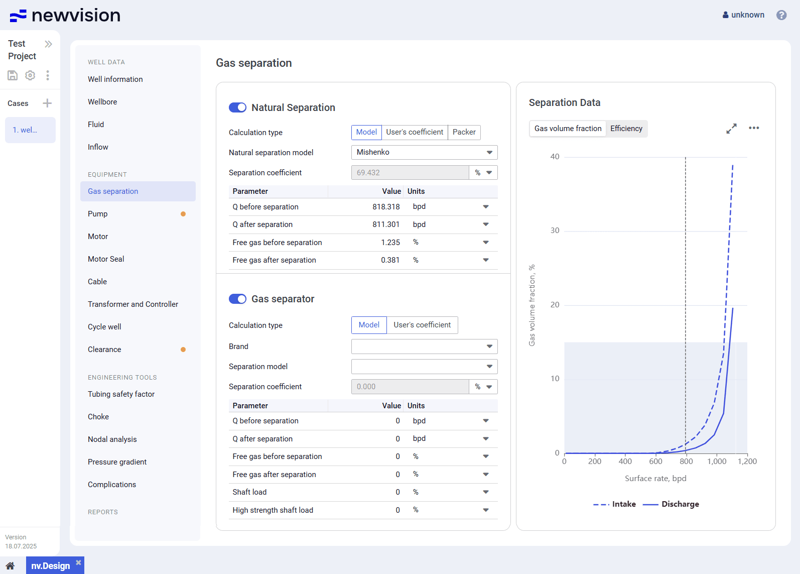
Gas separation: The Gas separation section provides information about the separation parameters at the pump intake. The section consists of the following parts: Natural…
The Gas separation section provides information about the separation parameters at the pump intake.
The section consists of the following parts:
- Natural Separation parameter group in the left part of the section.
- Gas separator parameter group in the left part of the section.
- Separation Data pane in the right part of the section.
 | Important Pump section models and target parameters such as surface rate and pump frequency from the section. Target tubing head pressure from the section. |
 Select image to enlarge
Natural Separation
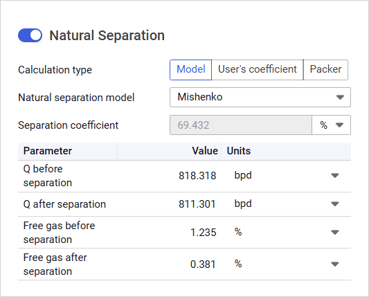
This parameter group provides controls for configuring the natural separation parameters.
 Select image to enlarge
To enable or disable natural separation, use the toggle to the left of the group name.
 | Note |
You can select one of the following calculation methods:
- Model: Calculation using one of the pre-defined models.
You can select the model from the Natural separation model list:
Mishenko: Simplified approach where key physical forces, such as friction and gravity are treated with limited detail. Instead, the model focuses on the representation of phase transitions, particularly the release of gas from oil within the wellbore.
It is commonly used under relatively simple well conditions and is especially effective when assessing gas liberation dynamics prior to surface separation equipment.
Alhanati: Comprehensive description of multiphase flow physics. The model is designed for scenarios where complex phase interactions must be considered. It is particularly suitable for directional and vertical wells, as it accounts for wellbore inclination, gravitational segregation, and phase slip.
Due to its higher accuracy, this model is typically applied in challenging operating environments where realistic modeling of fluid behavior in the wellbore is critical for performance optimization.
- User’s coefficient: Calculation using a custom user-defined coefficient.
You can enter it in the Separation coefficient field. - Packer: Calculation via simulation of a packer.
Below these controls, there is a table with the values of the flow rate (Q) and free gas content before and after separation.
Gas Separator
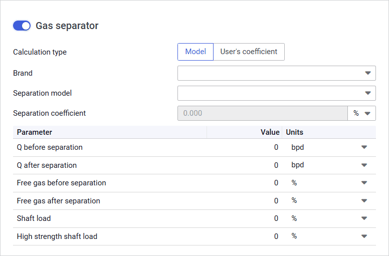
This parameter group provides controls for configuring the separation parameters if a gas separator is used.
 Select image to enlarge
To enable or disable mechanical separation, use the toggle to the left of the group name.
You can select one of the following calculation methods:
- Model: Calculation based on the specific gas separator model parameters.
You can select the separator by selecting its manufacturer and model from the Brand and Separation model lists respectively. - User’s coefficient: Calculation using a user-defined coefficient.
You can enter it in the Separation coefficient field.
Separation Data
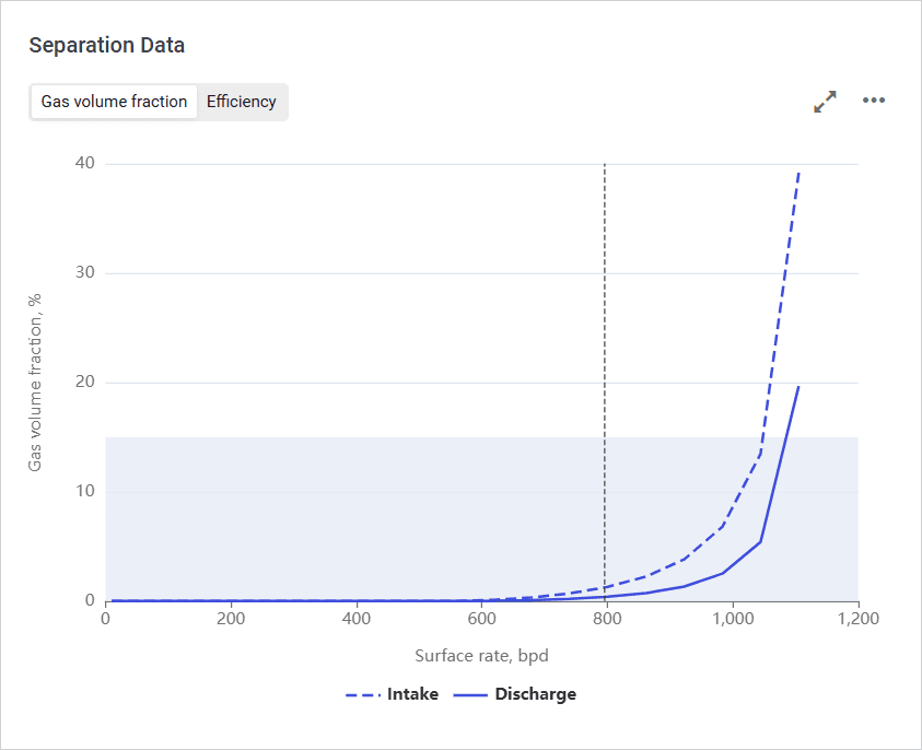
The pane provides visualization of the separation characteristics based on the parameters configured in the Natural Separation and Gas separator parameter groups (see description above).
The pane consists of two tabs:
- Gas volume fraction: Chart representing values of the gas volume fraction at intake and discharge depending on the surface flow rate.
 Select image to enlarge
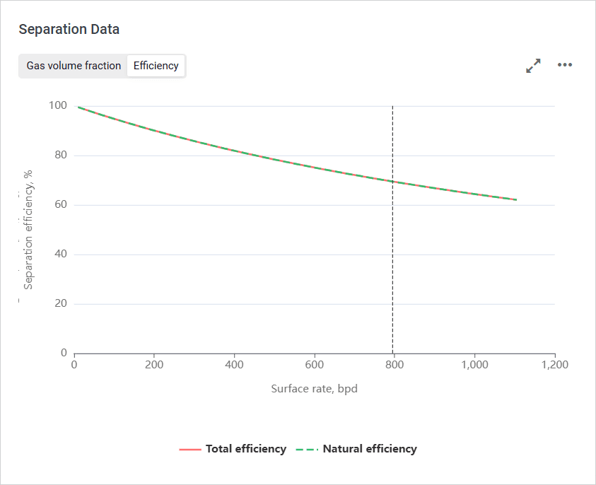
- Efficiency: Chart representing total, natural and/or mechanical separation efficiency depending on the surface flow rate.
 Select image to enlarge
To show or hide a parameter on the chart, click the parameter name under it.
On hovering over any point on the chart, a window with information about the exact parameter values at this point is displayed.
You can also expand the pane to full screen or collapse it back to the original size using the Expand ( ) / Collapse ( ) buttons located in the upper-right corner of the pane.

