After adding general well data, proceed to equipment design:
- In the Pump section, in the Calculation parameters pane, configure the calculation target parameters: enable two of the three available parameter groups: Well productivity, Stages, and Pump frequency. For details, see Pump.
In the Pump section, in the Pump selection pane, click Add ( ) and select the desired model for the first pump section.

 | Note |
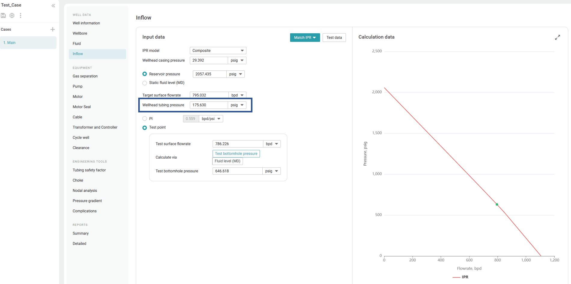
Go back to the Inflow section, and enter the target value for the Wellhead tubing pressure parameter.
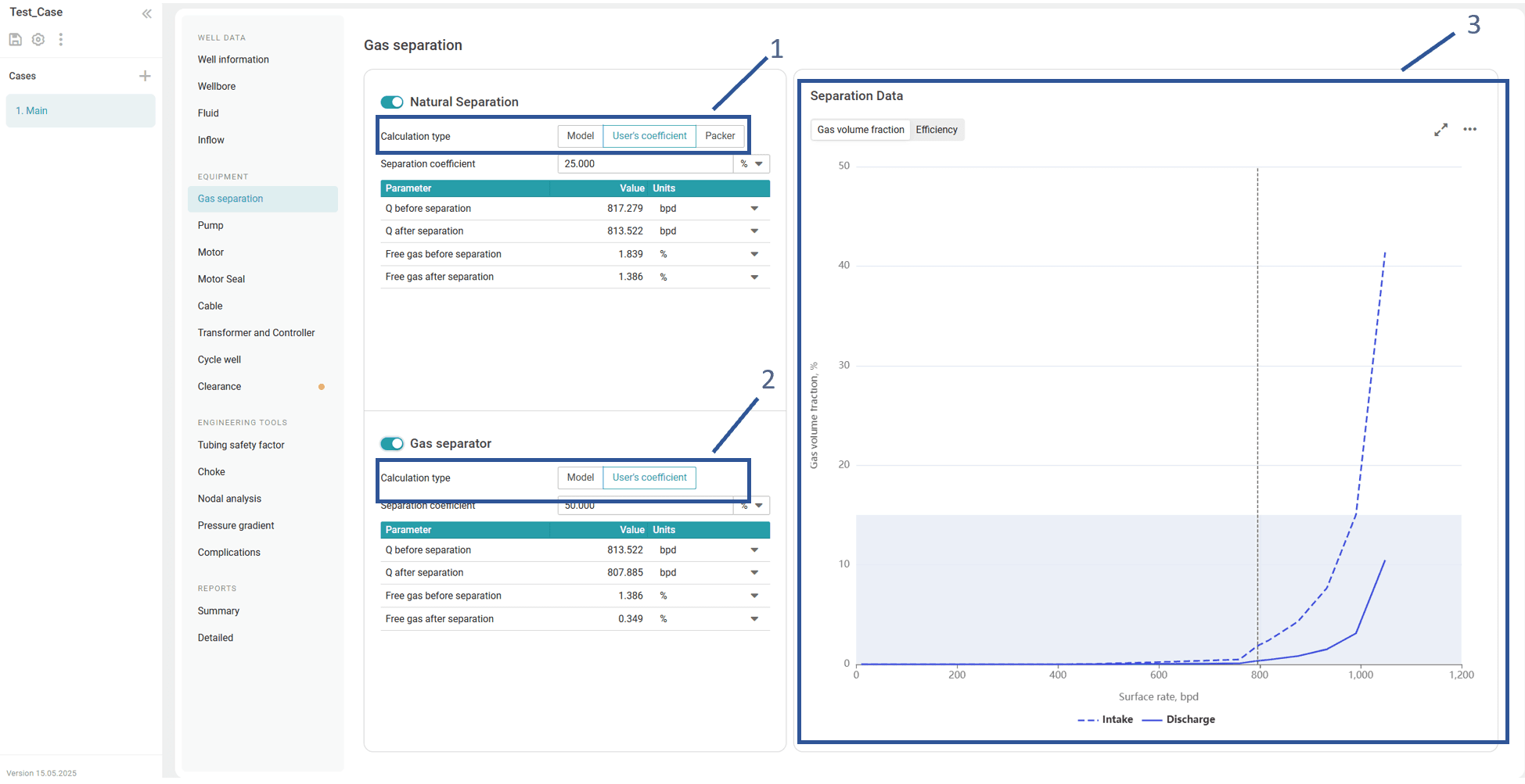
In the Gas separation section, configure the well natural, and/or mechanical separation parameters. The applied dynamic performance will closely reflect realistic conditions, taking into account variations in the separation coefficient depending on the production rate at the pump intake.
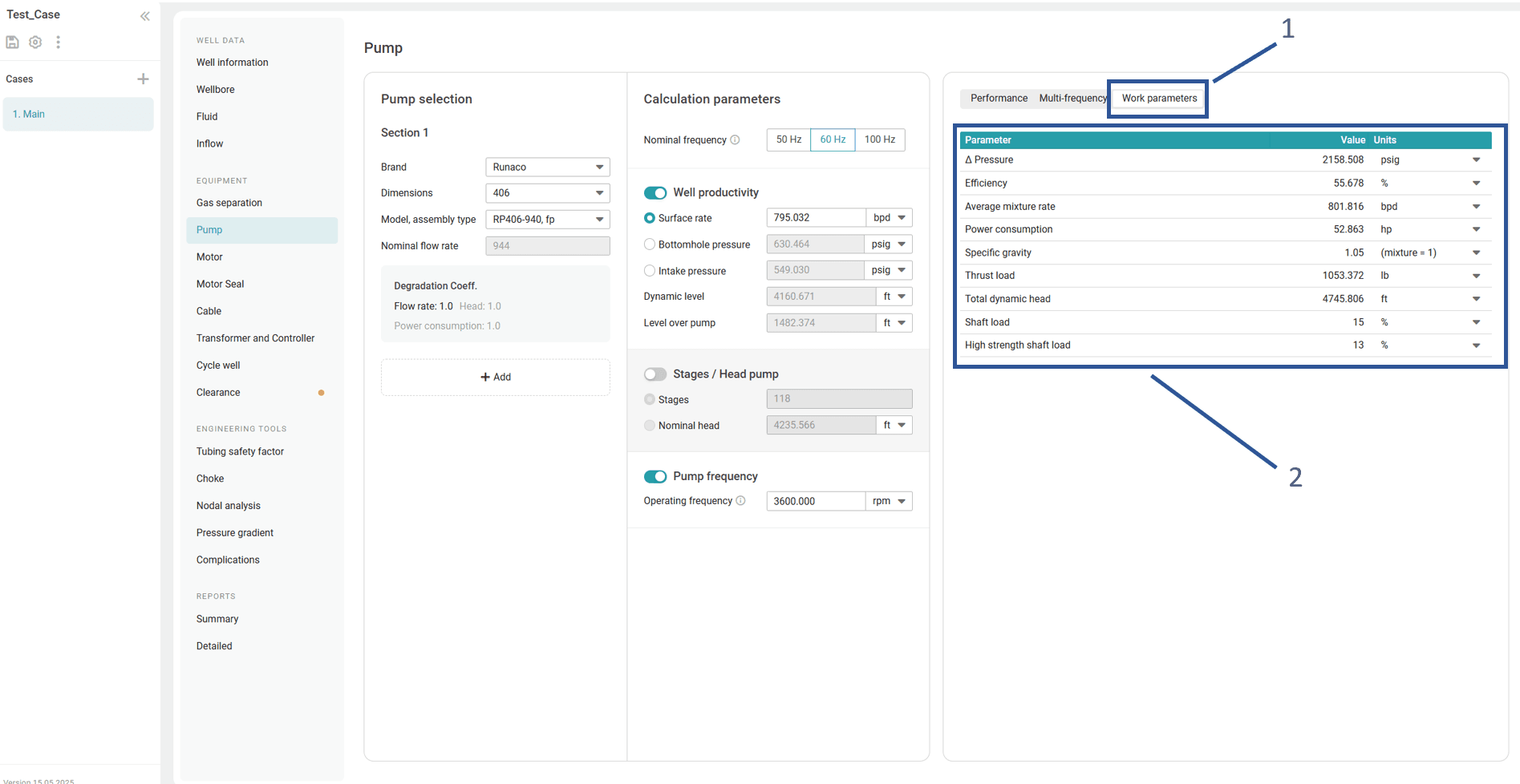
(Optional) Go back to the Pump section, in the upper-right corner of the section, click Pump derating factors, and then configure the flow rate, and power consumption derating factors for the pump sections. For details, see Configuring Pump Parameters.
In the right part of the Pump section, view the calculation results presented as curves (Pump performance and Multi-frequency tabs) and a table (Calculation data tab).
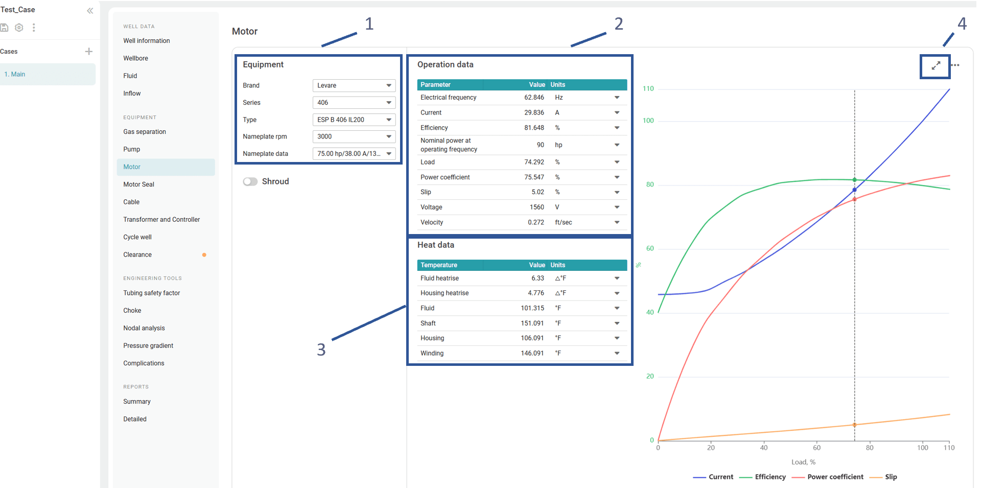
In the Motor section, in its left part, select a model of the motor that best suits the current parameters and, if needed, enable the Shroud option and specify the shroud inner and outer diameters. For details, see Motor.
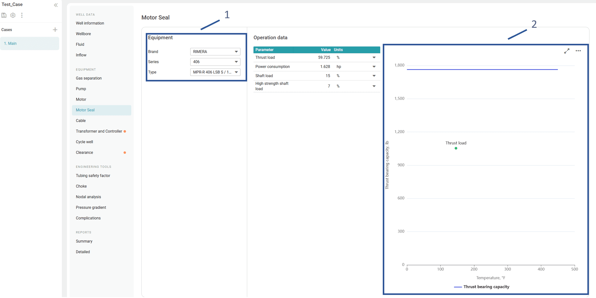
In the Motor Seal section, in its left part, select a model of the motor seal. For details, see Motor Seal.
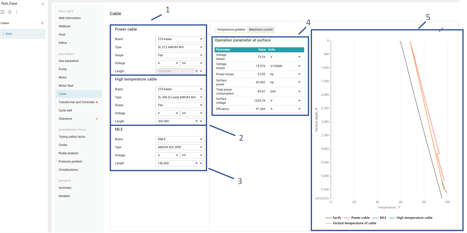
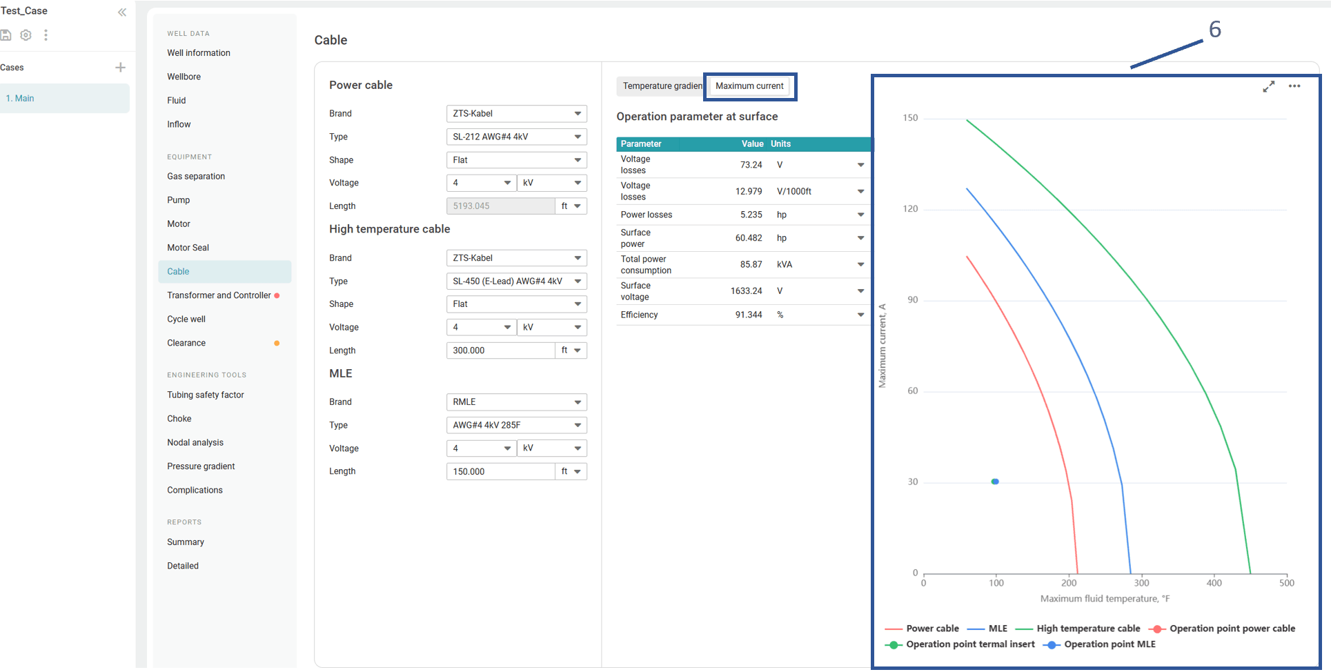
In the Cable section, select a power cable and, if needed, a high-temperature cable and a motor lead extension (MLE). For details, see Cable.
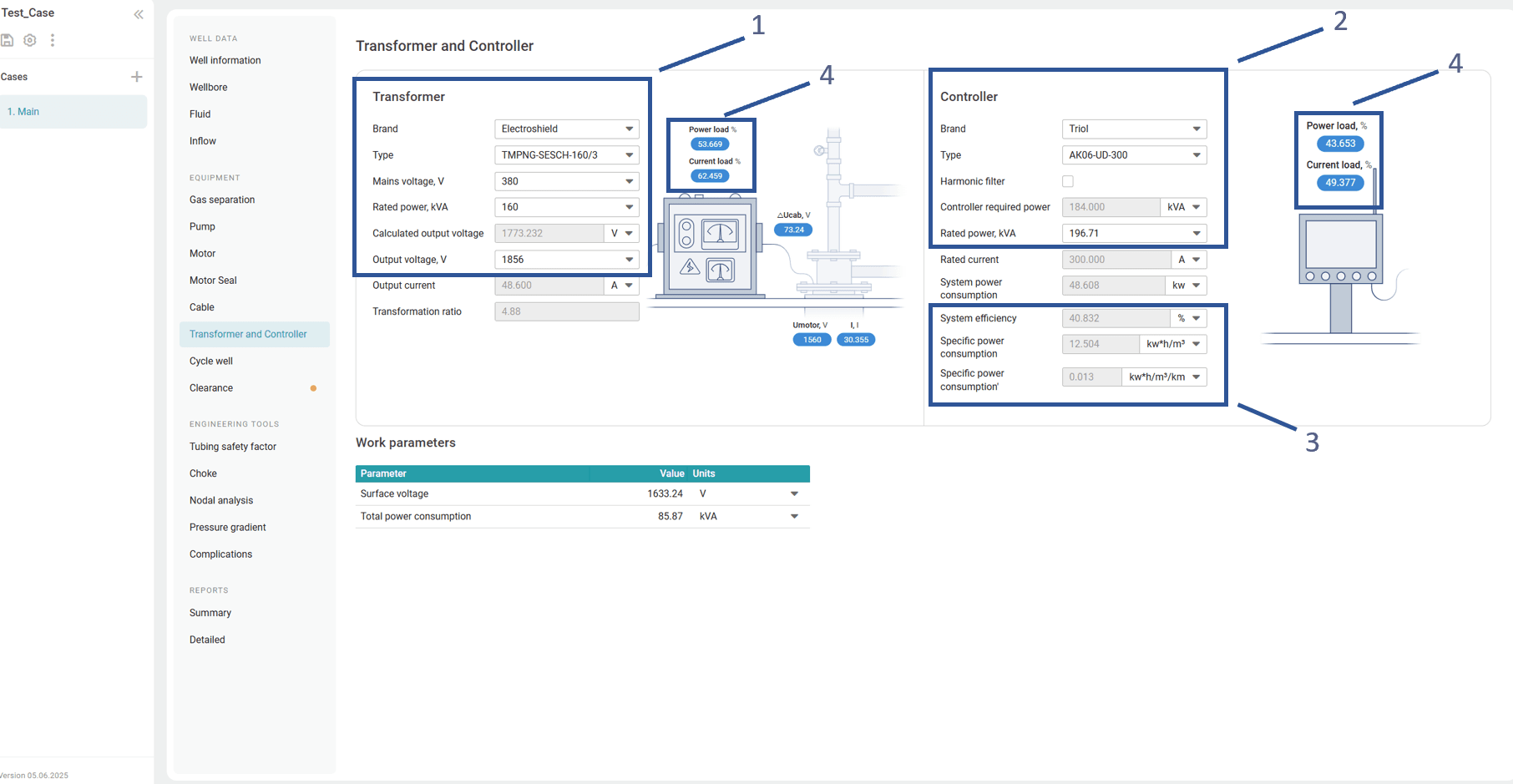
In the Transformer and Controller section, select the desired equipment models in the corresponding panes. For details, see Transformer and Controller.
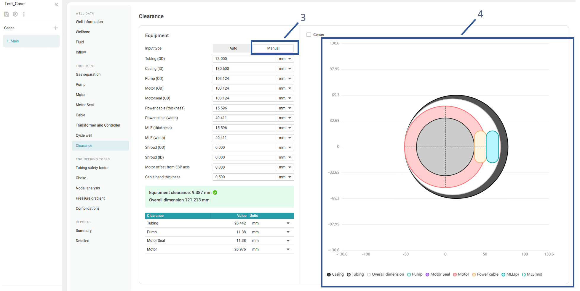
- In the Clearance section, where equipment dimension data is automatically imported from other sections. The system calculates the maximum equipment size and minimum clearance—both critical for defining operating conditions (1).
A useful feature allows alignment of the motor offset relative to other downhole equipment and accessories (2). Assembly alignment can also be adjusted to match the ESP and production string axes.
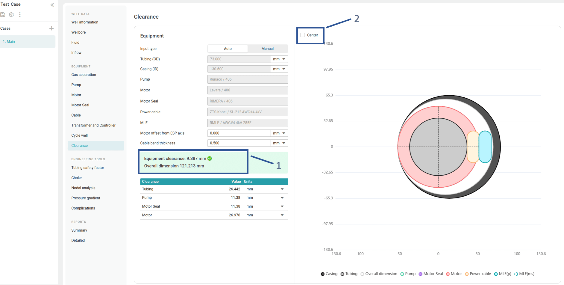
Manual input of equipment dimensions enables a quick check to determine whether clearance values fall within acceptable limits, even before detailed calculations are performed (3).
On the right, a simplified ESP layout inside the well is displayed (4).